
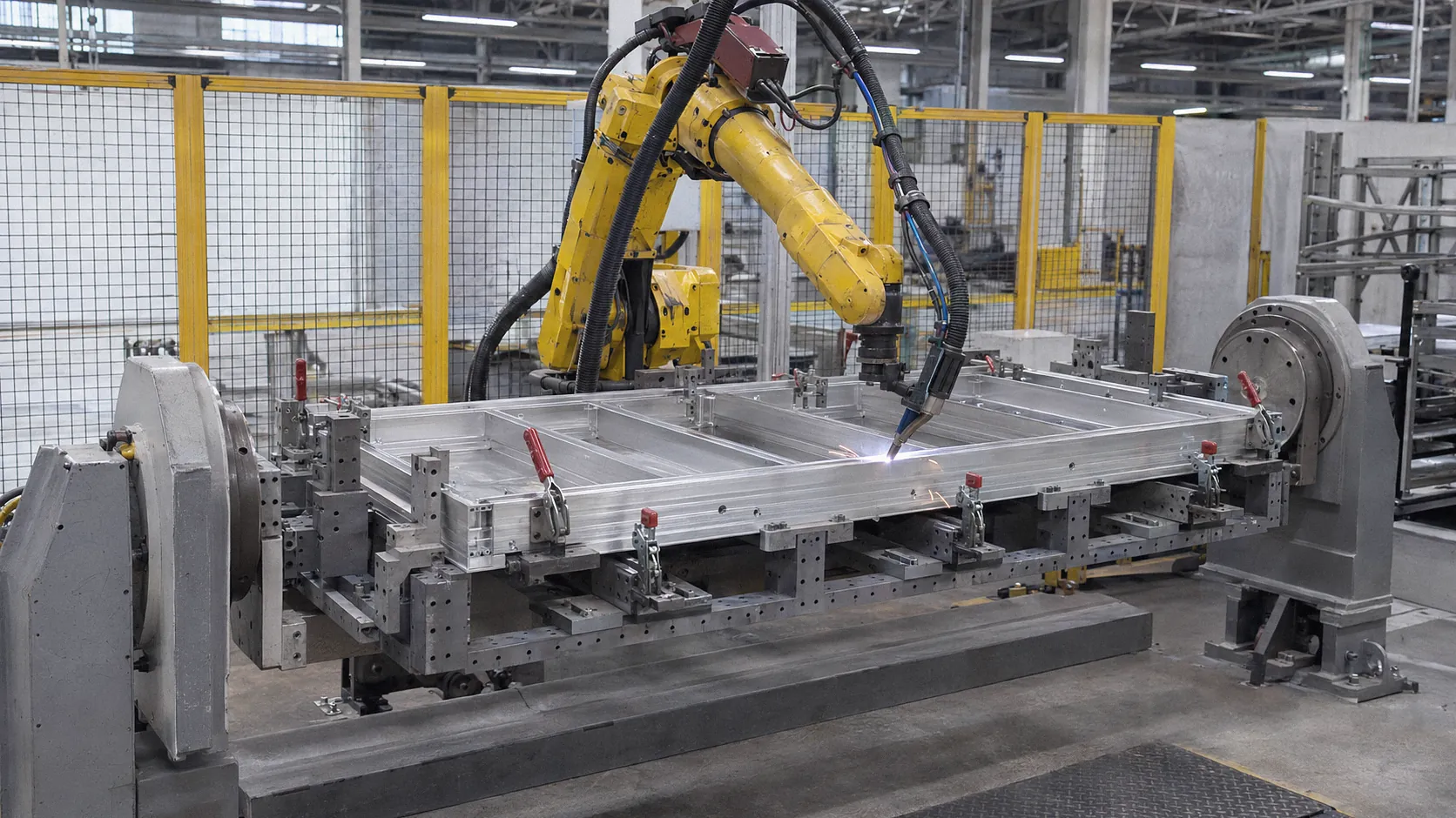
Aluminum battery tray welding joins the extruded profiles, and sometimes castings, that form the frame and tray of an electric-vehicle battery. Robot cells use MIG welding, friction stir welding or laser welding, depending on the joint, alloy and volume. The work is defined by three risks: porosity in arc welds, distortion along long thin-walled seams, and tightness of the finished tray. Fixtures, sensing, cleaning and testing are designed together to control them.
This guide compares the processes, explains porosity and distortion control, and lists what to plan into a line.
How battery trays are built
Battery trays and frames are mostly made from extruded aluminum profiles, joined into a frame and closed with a floor, sometimes with cast corners or nodes. A study in the Journal of Advanced Joining Processes, for example, covers joining extruded and high-pressure die-cast aluminum alloys “for battery frame assembly in BEV” by robotic friction stir welding.[1] In the EU ALBATROSS project, TWI joined extruded aluminum profiles of a battery tray by conventional friction stir welding.[2]
Processes compared
| Process | How it joins | Strengths | Points to plan |
|---|---|---|---|
| Robotic MIG (GMAW, often pulsed) | Arc melts filler wire into the joint | Flexible, robot-friendly, tolerates some gap | Porosity control, heat input and distortion, spatter |
| Friction stir welding | A rotating tool stirs the material below melting | Solid-state, no gas pores from melting; TWI notes it retains baseline strength and added no weight to the tray | High process forces, rigid fixtures, mostly linear seams, robot or machine stiffness |
| Laser welding | A focused beam melts a narrow joint | Low heat input, high speed | Tight fit-up, joint tracking, porosity in some alloys |
TWI points out that friction, ultrasonic and pressure welding avoid melting and therefore avoid gas pores,[3] and the ALBATROSS work reports that friction stir welding “retains the baseline material strength,” opening room for thinner material.[2] The JAJP study reached defect-free lap welds with stationary-shoulder friction stir welding at 3 to 15 mm/s, with tensile-shear strengths around 95 to 100 MPa at 3 and 5 mm/s.[1] Arc welding remains common where joints vary, seams turn corners or volumes do not justify friction stir equipment.
Preventing porosity in arc welds
Porosity comes from hydrogen. TWI explains that hydrogen has a high solubility in molten aluminum but is “approximately 20x lower” in solid aluminum, so it comes out of solution as the weld solidifies and trapped bubbles become pores.[3] The main sources are hydrated oxide films, contamination such as grease and skin oils, moisture drawn into the arc, and contaminated shielding gas.[3]
TWI’s prevention measures translate directly into line design:[3]
- Cleaning first. Cleanliness is the most important factor: degrease thoroughly before assembly, typically with a solvent such as acetone.
- Oxide removal close to welding. For stringent porosity limits, weld “within hours, rather than days” of oxide removal, and plan buffers accordingly.
- Separate aluminum work from steel fabrication to avoid cross-contamination from fume, grinding dust and shared tools.
- Dry, clean gas. Short gas lines, low-permeation piping, leak checks and a dew point “preferably below -50degC” at the torch; pre-purge lines that have stood idle.
- Steady arc. Prevent draughts and keep wire feed smooth.
- Welding conditions. Preheat, higher current or slower travel, or argon-helium shielding help hydrogen escape before solidification.
Controlling distortion
Long, thin-walled aluminum seams move as they heat and cool. Distortion is controlled by the fixture, the sequence and the sensing together:
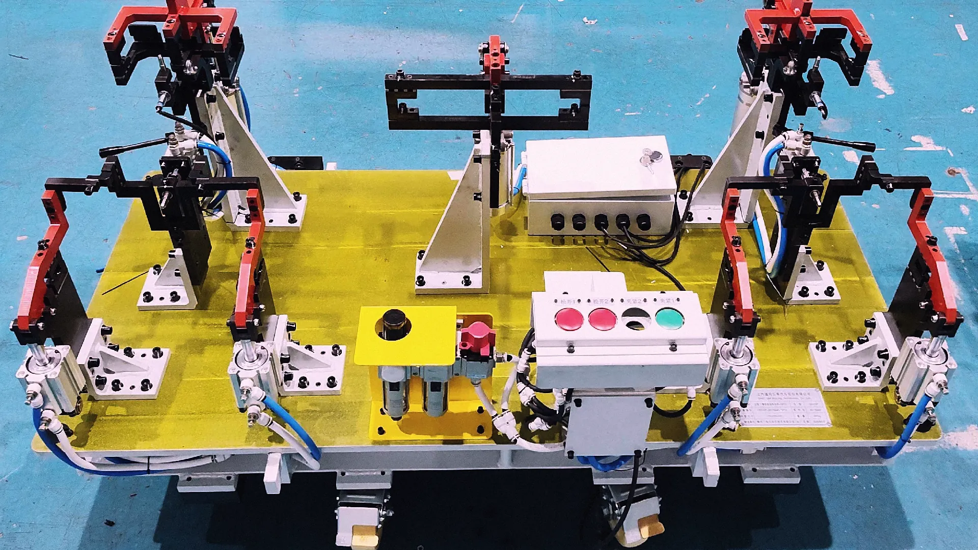
- Fixtures locate profiles on their datums and clamp close to the seams, with room for the torch. Our welding fixture design guide covers locating and clamping.
- Weld sequence balances heat, for example by welding opposite sides alternately and stitching before full seams.
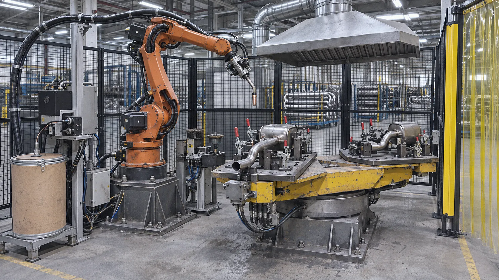
- Positioners turn the frame so seams are welded in the flat or horizontal position. See how a welding positioner works.
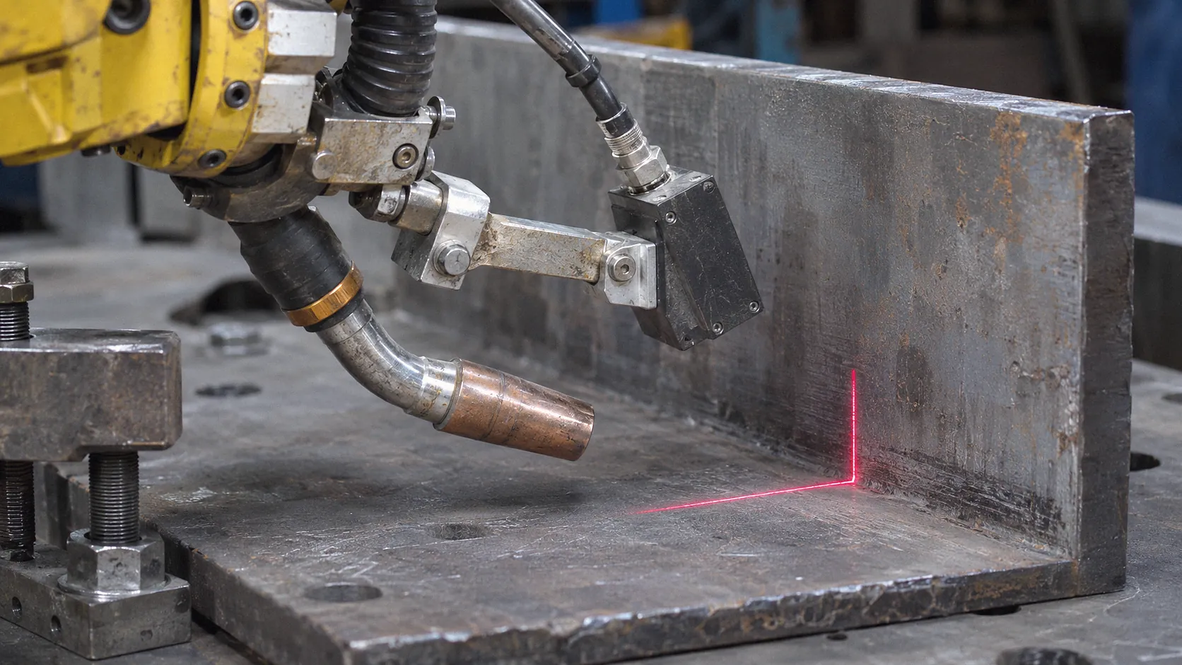
- Seam finding and tracking correct for profile tolerances and movement during welding. Yaskawa Motoman notes that laser seam tracking suits thin material with varying seams, and that laser point sensing finds lap joints down to 1/16 in. thick.[4] See our comparison of seam finding and seam tracking.
TWI measured distortion on three demonstrator friction stir welded trays in the ALBATROSS project,[2] a reminder that distortion is checked on real parts, not assumed.
Tightness, dimensions and traceability
A tray that must keep water and dust out is only as good as its weakest seam. Plan into the line:
- Leak testing of finished trays, with the test method and limits agreed with the vehicle maker.
- Dimensional checks of mounting points and sealing faces after welding.
- Weld records per tray: program, parameters, sensor corrections and any repairs.
- Repair rules: which defects may be repaired, how, and how repairs are retested.
Our guide on automation acceptance lists items to agree before handover.
How SanSong can help
SanSong’s published robotics cases include aluminum battery frame welding, and its product pages include a new-energy battery frame welding line that combines flexible fixtures with seam finding and tracking.[5] A SanSong film shows one of its robots welding an aluminum battery frame held on a head-and-tailstock positioner. SanSong also builds the positioners, tracks and complete welding lines.
To plan a battery tray or frame line, see robotic production lines, see automotive and new-energy applications or send us the tray drawing, alloy, joints and volumes.
Frequently asked questions
Which welding process is used for aluminum battery trays?
Robotic MIG (GMAW) welding, friction stir welding and laser welding are all used. The choice depends on joint design, alloy, thickness, production volume and requirements for strength, tightness and distortion.
Why does aluminum weld porosity happen?
Hydrogen dissolves readily in molten aluminum and is about 20 times less soluble in solid aluminum, according to TWI. As the weld solidifies, hydrogen comes out of solution and trapped bubbles form pores. Hydrated oxide, contamination, moisture and contaminated shielding gas are the main sources.
How do I prevent porosity when robot welding aluminum?
Degrease thoroughly, remove oxide shortly before welding, keep aluminum work separate from other fabrication, use leak-free low-permeation gas lines with a dew point preferably below -50 °C at the torch, and keep wire feed and shielding steady.
What does SanSong supply for battery frame welding?
SanSong’s published products include a battery frame welding line with flexible fixtures and seam finding and tracking, and its robotics cases include aluminum battery frame welding.
Sources
- Robotic friction stir welding in lightweight battery assembly of extrusion-cast aluminium alloys, Journal of Advanced Joining Processes, vol. 8, 100156 (Patel et al.), .
- ALBATROSS project concludes, TWI, .
- Avoiding porosity when welding aluminium, TWI.
- Pros and Cons of Robotic Seam Finding and Seam Tracking, Yaskawa Motoman (Josh Leath), .
- Application cases of industrial robots and automation systems, SanSong (lzsansong.com).
Editorial note: written from the public sources listed above and SanSong’s published product information, checked on the dates shown. It is general guidance, not legal or compliance advice. Specifications not yet published by SanSong are confirmed during the project review.